Old post from other journal:
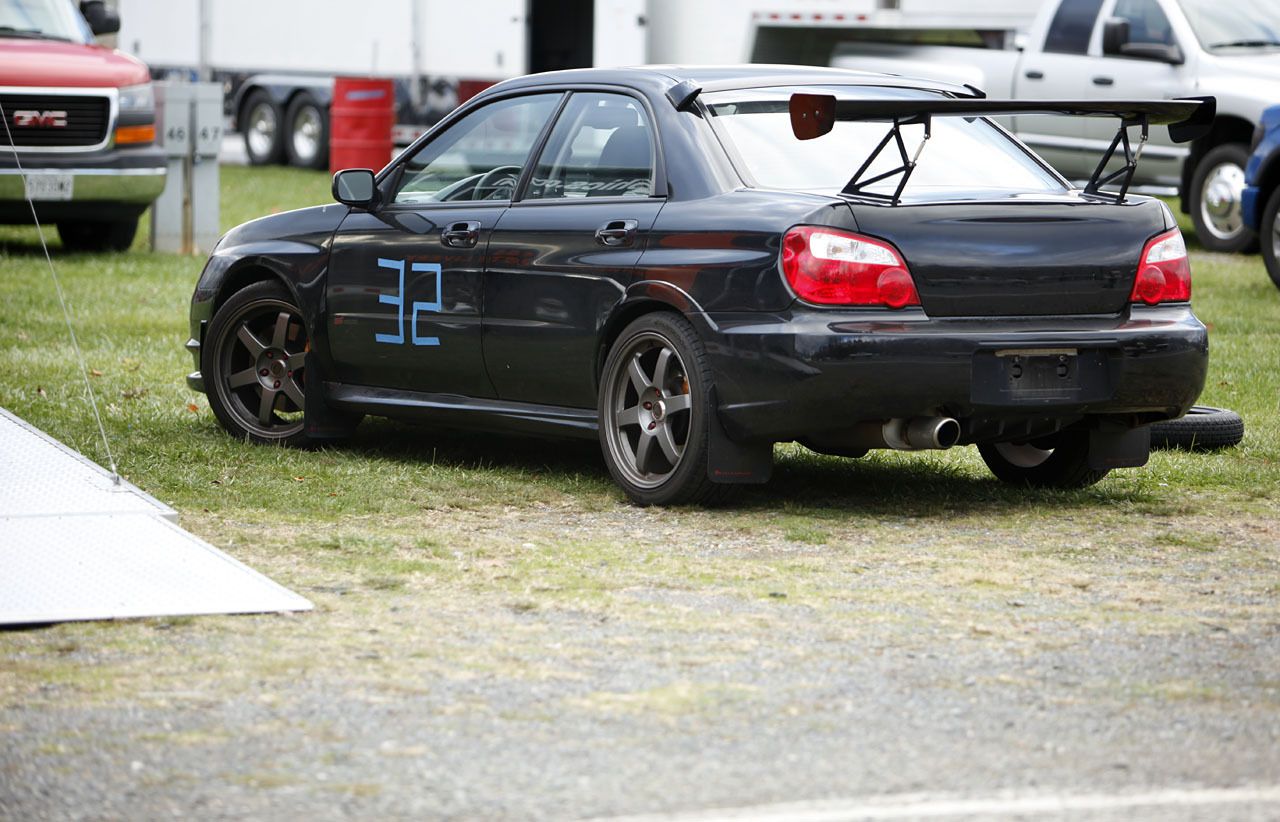
I was just reminded that my undertray came off on track. You can see it dangling in a few pictures above! I had my undertray zip-tied on, but it came undone somehow in my first track session. As it was bent backwards pretty might the whole left side of it ground away and I ended up throwing it out at the track. I PLAN on mocking up some cardboard in a fashion similar to this:
DIY Front Undertray - NASIOC or this:
http://www.iwsti.com/forums/how-install/161079-skidplate-under-armor-made-easy.html
and then transfer the design to sheet metal
But I think i would add some louvers, similar to this:
http://www.iwsti.com/forums/2070591-post18.html
More links (for later reference)
DIY Front SkidPlate/Aero diffuser - NASIOC
DIY splash guard/skid plate? - NASIOC
DIY Total Underbody Protection - DirtyImpreza Forums
DIY skid plate - NASIOC
---------------------------------------------------------------------
Here's the background. I removed my front subframe and attempted to merely zip-tie the factory splash-guard back into place. The splash guard came off on one side on the freeway (which i managed to fix) and then self-destructed on the track. I decided i needed a piece there, both for engine protection and for aero, but I couldnt find any undertrays that would fit without the front subframe:
Hey guys, so i've been talking with T3h_Clap and I think we're onto something (ok, it was mostly him).
Basically its a skeleton for the diffuser that will bolt to the car. Right now I'm thinking of just four mounting points:
2x front jacking plate
2x front frame (see pic below)
The front would be mounted to the same two holes you see his piece mounted to.
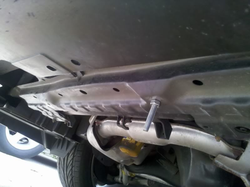
Now, on my car only ONE of those holes is threaded so I've ordered some nutserts to turn it into a threaded hole. If anyone's wondering the existing thread is M8x1.25, so that's what i ordered.
So into those two holes I'd put two long threaded rods, with a nut to keep them in place. The frame would mount flush with the jacking plate, and thread onto the rods. To allow different front clearances (for different lips, etc...) the front of the skeleton would be sandwiched between two other nuts.
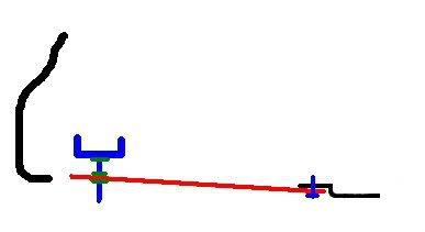
I did a 30-second paint illustration:
The black is the front bumper and jacking plate. Blue is frame and bolts. Green are the nuts.
I plan on mocking up a skeleton/frame out of wood in the next week or so, and then seeing if a fab shop can make me something cheaply. Here's an example frame:
From there it would be easy to:
a) weld frame to the skidplate
b) bolt it
c) whatever else.
---------------------------------------------------------------------
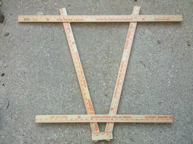
It finally stopped raining so i managed to get outside and mock up a preliminary frame out of yardsticks.
In case you're having trouble reading dimensions:
Distance between mounting holes:
Each diagonal is almost exactly 22"
Across the front is 14.25"
Across the rear is: I believe 3" but i need to double check
From back of plate to rear holes is: I thing its 1.25" but I also need to double check
On the other hand, after assembly of a metal version, i may decide that it's not rigid enough and add more triangulation.
Other important dimensions:
jacking plate bolt separation: roughly 2.75"-3"
Frame bolt separation: roughtly 14.25"
Front-to-back-diagonal: roughly 22"
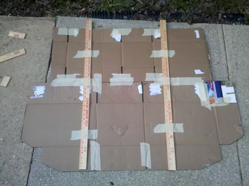
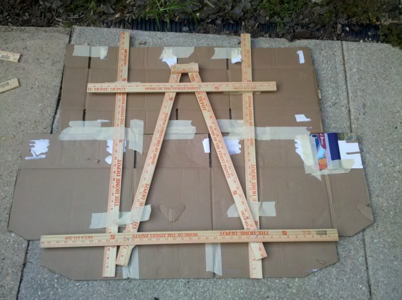
I'll tweak it more and post up some dimensions later, but here are some teaser pics:
The two extra yardsticks are just to help keep the cardboard rigid while i tweak with it off the frame.
---------------------------------------------------------------------
Well home depot has 36"x1"x1/8" aluminum bars for like $6 each or something like that. So i got four, but unfortunately i had to buy a lot of supporting tools too, but I'm sure I'll find good use for them!
Anyways, more details: The hole i was hoping to nutsert isnt big enough for the size thread (m8x1.25) as the threaded hole. My new plan is to spot-weld (maybe glue/epoxy) a nut in place on the underside of the beam over where the hole is. I also need to get a bigger drill bit to make the holes for the bolts in the aluminum. Once those are drilled I can then go about test-fitting and riveting the frame together. Then comes the aluminum flashing.
Hopefully more pics/details/instructions will soon follow!
---------------------------------------------------------------------
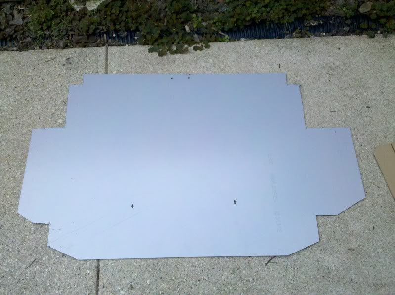
I've got v1.0 of the undertray completed.
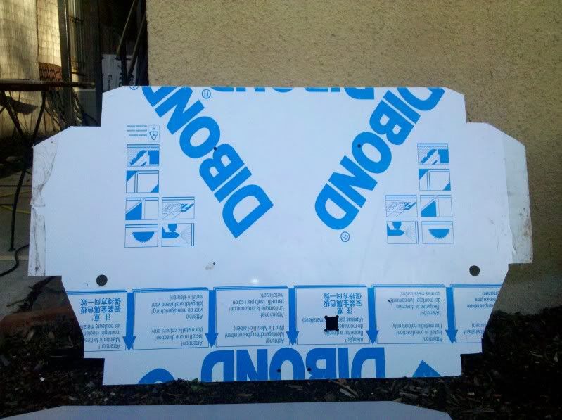
I've scrapped the original idea of the skeleton with the undertray attached, as my new material is significantly thicker and less "bendy." Its scrap from a friend's splitter project, so I'm not sure the technical name for it, but it consists of thin aluminium sandwiching some PVC. Consequently its very light, but very stiff and easy to work with. Ideally, i'd have the piece be maybe 4" wider than it is, but i got it for free so I can't complain. You can see that the piece isn't symmetrical, as one "wing" is bigger than the other. That's where i'd like the extra 4" on the other side.
Here's a pic of the cutout:
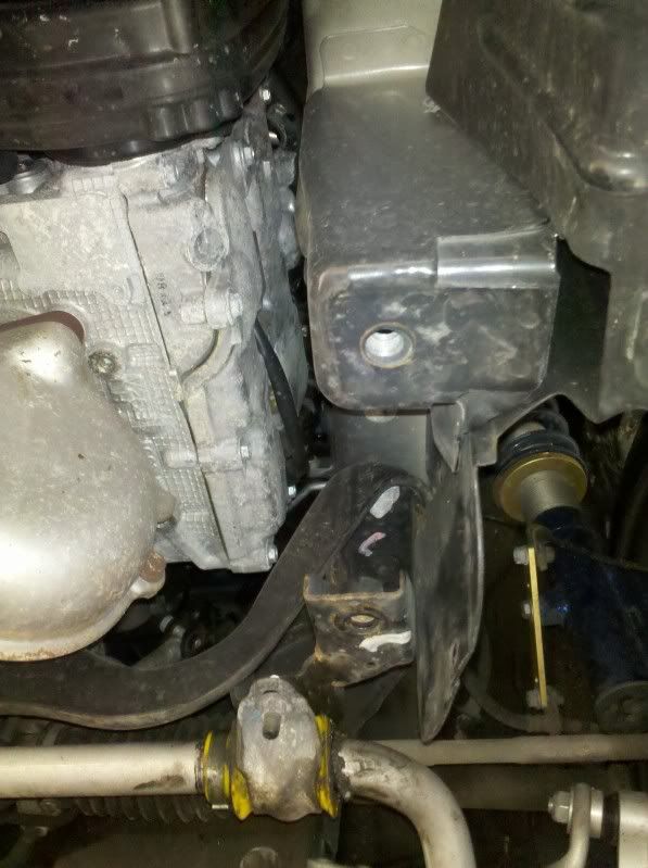
So as I mentioned before, the front frame has two mounting holes, only one of which is threaded:
I attempted to JB weld a nut over the second hole but i dont think i scuffed the surfaces properly and the nut was not very secure. I'm trying the JB weld again tonight. If that fails, I'll get the nut spot-welded in place.
For test-fitting I was unable to get the front passenger side properly secured, due to the lack of the threaded hole, but there *may* be a flutter issue with the wings of the plate. I've identified two holes on each side that i might use (either/both) if this ends up being an issue. If i decide i need to use those holes, it might require cutting a new tray, as the holes are very close to the corner in the big cutout towards the rear of the tray.
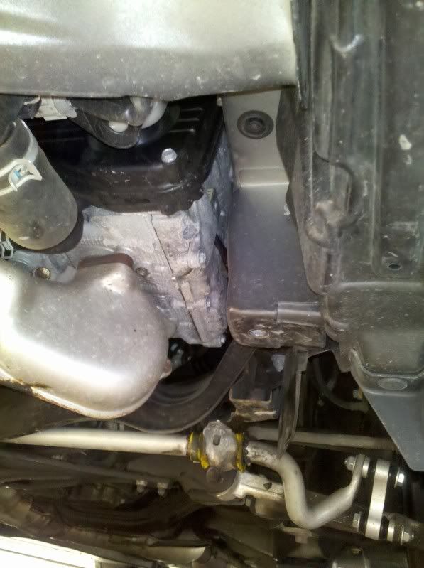
Here are the two mounting points to which I'm referring:
The hole closest to the front looks preferable to me, as it is farther towards the edge of the car. The plate is almost exactly 3" below the hole, so if i decide to use that mounting point we'll see if i end up with a spacer or just a sandwiched-nut type thing.
---------------------------------------------------------------------
It turns out my holes were just a little off. I re-measured and managed to drill out the existing holes without making them overly large.
I installed the undertray as-is (without the extra side supports) and I'm awaiting my first test drive. My initial impression is that the extra supports are not going to be needed that far back, but maybe further forward on the "wings." We'll see!
---------------------------------------------------------------------
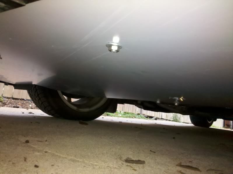
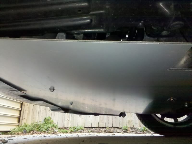
The tray works wonderfully! And by works I guess I mean doesn't have any horrible problems. It's hard to judge any protection or fuel economy benefits, but I drove about 60 miles and hit speeds of about 75 mph without any issues.
I did an oil change as well, and installed a Fumoto drain plug--the one with the nipple. The clearance was such that I had to make a cutout for the fumoto, as the nipple protrudes slightly below the undertray. I did a mediocre job on the cutting, as it was a bunch of holes drilled out, taking many iterations. Since this is still my "V1" undertray I'm not too concerned. I can decide where, and how big, the hole should be for the V2 if/when I decide to go that route.
If i had it to do over again, i would JB weld the nut to a large fender washer. It was a pita to JB weld that under the car. I had a problem with the nut not holding. Anyways, I'd then JB weld the fender washer to the car, and have a lot more surface area holding it on.
Here are a few quick pics of the completed thing on the car. Sorry for the quality but the car's not jacked up and I'm using a cellphone.
Distance between mounting holes:
Each diagonal is almost exactly 22"
Across the front is 14.25"
Across the rear is: I believe 3" but i need to double check
From back of plate to rear holes is: I thing its 1.25" but I also need to double check




.jpg)
